Prusa Mini XYZ Calibration
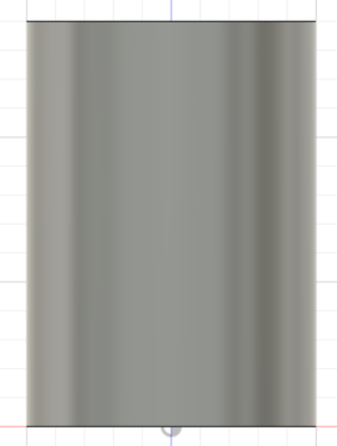
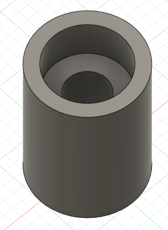
I have a 14mm tall (Z-Axis) cylinder 10mm diameter cylinder with an M4 hole printed in PETG. Two issues with this part are:
The print is too tall. This should be 92 layers @ 15mm layer height and 0.40mm first layer. This should me 14.05mm in height. Consistently, my Prusa Mini is printing 14.20-14.25mm. That’s way too tall, something is wrong here on the Z-Axis.
The print lines are too thick. There should be 7 layers @ 0.40 width which should leave plenty of space for the M4 bolt hole. Something is wrong in the line width making the walls thicker than the sum of the traces.
Step 1 in troubleshooting a tall print was to check the XYZ calibration.
A Bad Z Distance
This should be 14.05mm. The 0.24mm difference is significant. The cylinder diameter is correct @ 10mm but the layer widths are too thick causing the M4 hole to be too small.
What is XYZ Calibration?
The printer has NO real idea how far it travels. This is a value based on the physical components of the hardware. The assumption is that if for N steps in the motor, through the pulley (or whatever mechanism in the axis) will lead to a real world translation of T distance. If this value is off the N steps in the motor might translate to T’ distance in the real world. This T distance error is often very, very small but enough to cause your prints to be off. In my case, I found all axis about +/- 0.30mm. I’m shooting for ~+/- 0.05mm margin of print error.
XYZ calibration requires you to print a calibration part with known distances for each of the axis. The one I used is from here. Note, there is an orientation to the piece, so follow the directions closely. Don’t accidentally swap the axis on the slicer. Once printed, the actual printed distances are measured using a caliper then referenced along then requested distance. A formula is then applied and a manual GCode is inserted into print instructions. This will calibrate for the slight variances in logical to physical distances based on your Prusa Mini’s assembly.
I believe Prusa Mini in the firmware has a built in GCode M92 value of X100 Y100 Z400. This is confirmed by the test print and others experiments [ 1 ]
The M92 gcode is basically the number of steps on the motor to print a certain distance (includes pulleys, motor type etc). This makes sense as you notice the Z-axis has a value 4x the of the X and Y axis which correlates to how the printer can vary the layer height due to a much finer stepper motor control.
The formula is:
( Desired Printed mm ) / (Actual Printed mm) * (GCode Setting)
For example, if I printed a 100mm X-axis and I got 99.80mm physically printed the formula would be:
(100mm)/(99.80mm) * 100.0 = 100.20
I would then insert custom G-Code reading
M92 X100.20
This should tweak the number of actual motor steps per actual real world distance traveled. Rinse and repeat for all remaining axis then the final value would look something like this:
M92 X100.18 Y100.25 Z397.06
For Prusa Slicer, you can put this value under Printer Settings -> Custom G-Code -> Start G-Code -> Right After the phrase G90; use absolute coordinates
XYZ Calibration Print
Below are the three measurements of my X, Y, and Z prior to adjusting for the travel error. You can see that all axis are not quite 100mm nor 40mm (Z-axis).
Notably, the Z-Axis overprinted 0.30mm over the expected 40mm.


XYZ Calibration Final Result
I ended up with a value of
M92 X100.18 Y100.25 Z397.06.
This reduced the final error to -0.08mm, -0.04mm, +0.04mm on the XYZ respectively. This didn’t fix the issue with the tall print, but at least I know that this travel distance is calibrated and this shouldn’t be acerbating the issue along the Z-axis. This also means that I have some confidence that larger pieces won’t accumulate too much error in the directional axis.
In places where the 3D print accuracy isn’t important, most users may not care. The variances are small < 0.40mm over 100mm (0.4%) on the XY and < 0.4mm on the Z (0.75%). If you are printing for dimensional accuracy, it’s worth doing this step.


